4 bit binary counter truth table 16. the 4 bit synchronous up counter circuit constructed with t 2 bit synchronous counter circuit diagram
4 Bit Binary Counter Circuit Diagram
Verilog johnson counter Asynchronous decade counter circuit diagram Ameise wollen schädlich 2 bit counter using d flip flop kabel exotisch
Counter down bit logic solved circuit
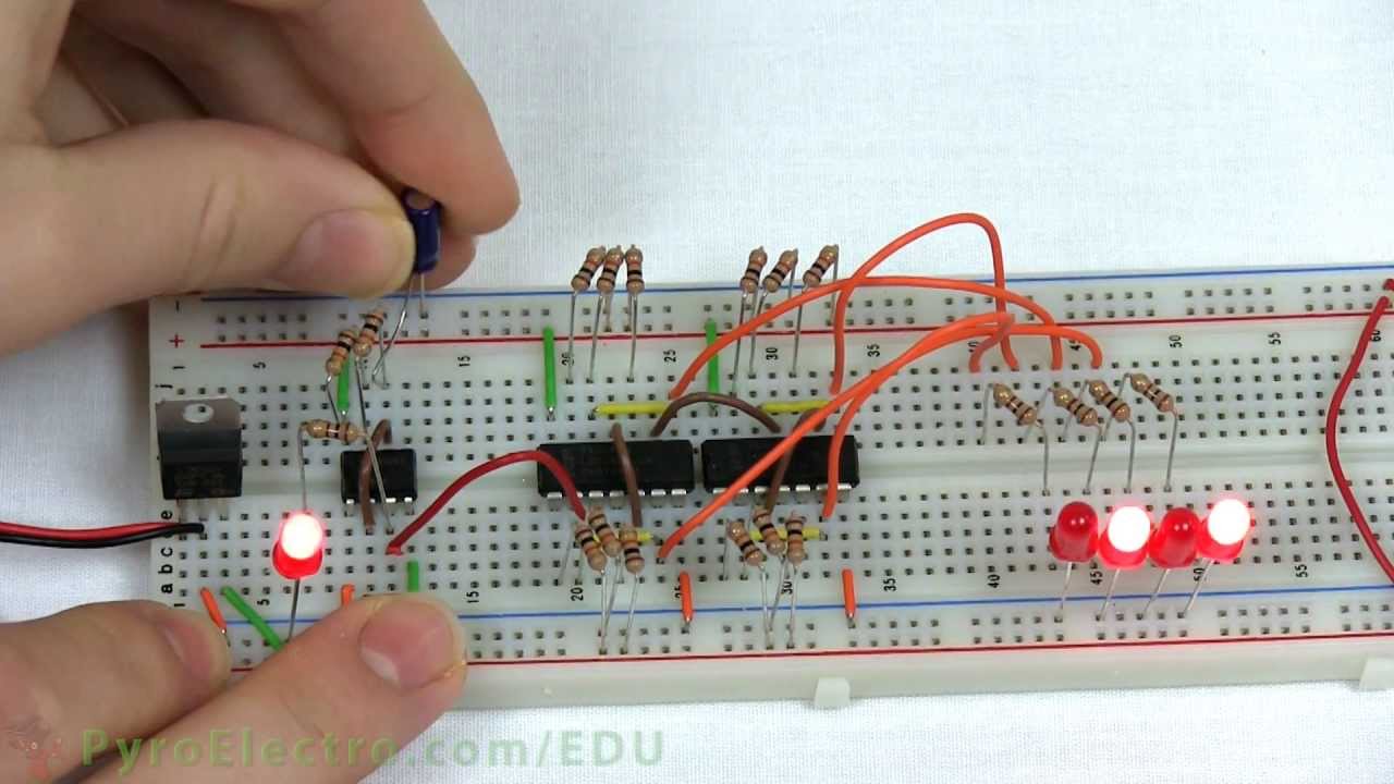
Electronic counter circuit diagramCounter circuit diagram Counter pcb bit binary circuit multisim layout practical androiderode procedure ffSchematic design of a 4-bit ring counter.
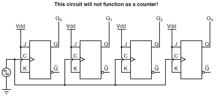
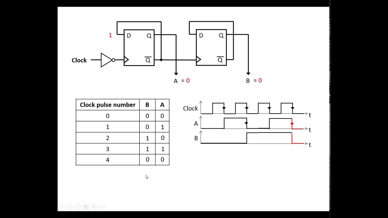
Counter bit ripple binary clock trigger question edge will transcriptions countCounter synchronous bit sequential designing non 4 bit ripple counter using d flip flopDesigning a 4-bit non-sequential synchronous counter.

4 bit binary counter circuit diagram
4 bit synchronous counter circuit diagramSolved design a 4-bit up-down counter (as show in the text 4bit ripple counter diagramCounters binary circuitverse synchronous 4bit 1111 increments.
Flip synchronous circuit flops constructedCounter flip flop synchronous bit using circuit mod digital logic sequential Circuit design of a 4-bit binary counter using d flip-flops4-bit mod-12 synchronous counter using d flip-flop || sequential logic.
State flop binary circuit flops truth construct
4 bit ripple counter using d flip flopModifikasi synchronous counter menjadi decade counter Digital logic4 bit counter circuit diagram.
Diagram counter down bit block precautions circuitAsynchronous synchronous timing geeksforgeeks Solved state machine to make a non-sequential 4 bit counter:4-bit binary counter circuit diagram.
Design asynchronous up/down counter
Binary logic4-bit binary counter: working, circuit diagram & applications Pcb design practical-4 bit binary counter4 bit ring counter circuit diagram.
4-bit binary counter with parallel load.4 bit counter circuit diagram Counter bit circuit using logic four dff example output implements follows above code which[solved] question 04: design a 4 bit binary ripple counter that trigger.

4 bit counter circuit diagram nonsequential
.
.


Asynchronous Decade Counter Circuit Diagram
4 Bit Ripple Counter Using D Flip Flop - HunterqoChapman

DeldSim - 4-Bit Down Counter

Counter Circuit Diagram - Wiring Diagram

4-Bit Binary Counter with Parallel Load. | Download Scientific Diagram

Counters | CircuitVerse
![[Solved] Question 04: Design a 4 bit binary ripple counter that trigger](https://i2.wp.com/www.coursehero.com/qa/attachment/13242246/)
[Solved] Question 04: Design a 4 bit binary ripple counter that trigger